Schemas
Electrical diagram
- The 4N35 optocoupler is connected to pin 8 of the Arduino. It is used to transmit an opening electric lock signal.
- The buzzer is connected to pin 9. It is used to generate a beep when a key is read and beeps to confirm or not the openning of the door
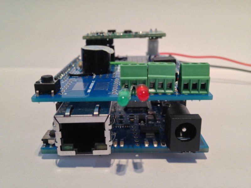
- The green LED is connected to pin 6. It is used to generate a visual confirmation of the opening of the door.
- The red LED is connected to pin 5. It is used to have a visual confirmation that the door remains closed.
- The RFID reader transmits is data on pin 2. A serial port is emulated on this pin.
- Ethernet port and SD card reader are connected to pin 10 and 4. These pins can not be changed.
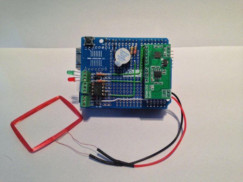
Fritzing
- The LEDs were placed on a terminal to facilitate the testing and to allow to easily add a cable to put them out of the lock.
- The RFID reader has to be connect the top right on the female headers.
 WebLock lock
 WebLock lock
 Manage of the users
 Access history